ThreatModel - Data Flow Diagram legend
-
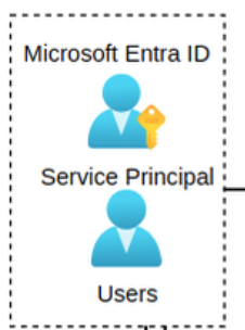
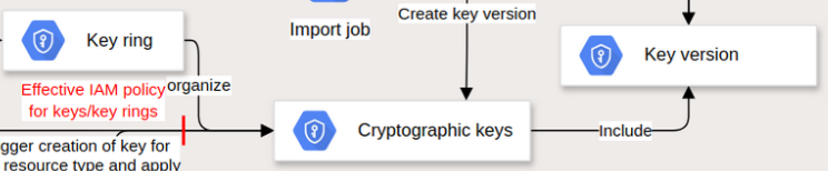
Components: Usually the icons (like service, IAM entity, etc.) represent a point of input/output or somewhere there is some data which is processed/stored/transmitted
-
Azure example: Users and Service Principals in Entra ID
-
GCP example: Key ring, cryptographic keys, and key version in Cloud KMS
-
-
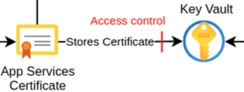
Flows: The links between components (Network, API, AWS fabric). It must be an actual flow of data (not a functional relationship). The arrow starts from the service that initiates the flow.
-
Azure example: App Services certificates are stored in a Key Vault.
-
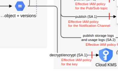
GCP example: Cloud Storage objects can be encrypted with a CMEK in Cloud KMS.
-
-
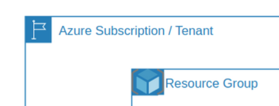
Context: Where the components are (Account, Region, etc.)
-
Azure example: Azure Tenant, Subscription, or Resource Group.
-
GCP example: GCP resource hierarchy: Organization, folder, project, service, VPC

-
-
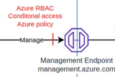
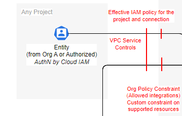
Boundary: The things that can stop/restrict a flow, should be placed next to the component they are attached to, or close to.
Azure example: The proper RBAC, conditional access policy, and Azure policy requirements need to be met in order to manage an Azure resource.
- GCP example: Effective IAM policy for the project and resource, VPC Service Controls, and Org policy constraints need to be met to manage a GCP resource.
- GCP example: Effective IAM policy for the project and resource, VPC Service Controls, and Org policy constraints need to be met to manage a GCP resource.